IR sensor housing
Design and fabrication of a housing for the IR sensors and electronics of a smart white cane.

About the project
For the final team project of my exchange at the Singapore University of Technology and Design, my task was to design a housing for the IR sensors of our smart white cane.
The first iteration had many problems. My teammates hadn’t given me the dimensions of the electronic components that were meant to go inside, so I guessed them.
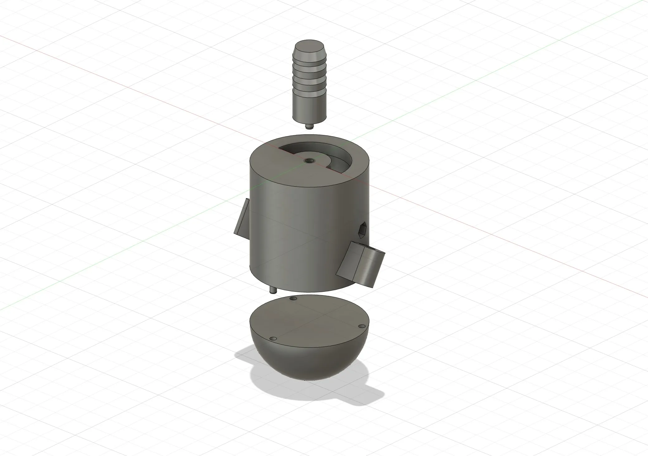
The design consisted of a pin that formed an interference fit with the cane. It was pressed via a peg into the main body of the hollow cylindrical housing, which had two protrusions on the sides for the IR sensors themselves. A hemispherical “cap” was then pressed onto the body with pegs.
The main problem was the pegs. It was hard to size the pegs and holes so they would fit together yet still hold. On top of that, the pegs were so small that they tended to snap even under light load. The material of the first prints was PLA.
The second design aimed to solve assemblability. It had been hard to fit the electronics into the first design because it was relatively closed. So for the second design I moved away from the “cap” concept and decided to make the body a split cylinder.
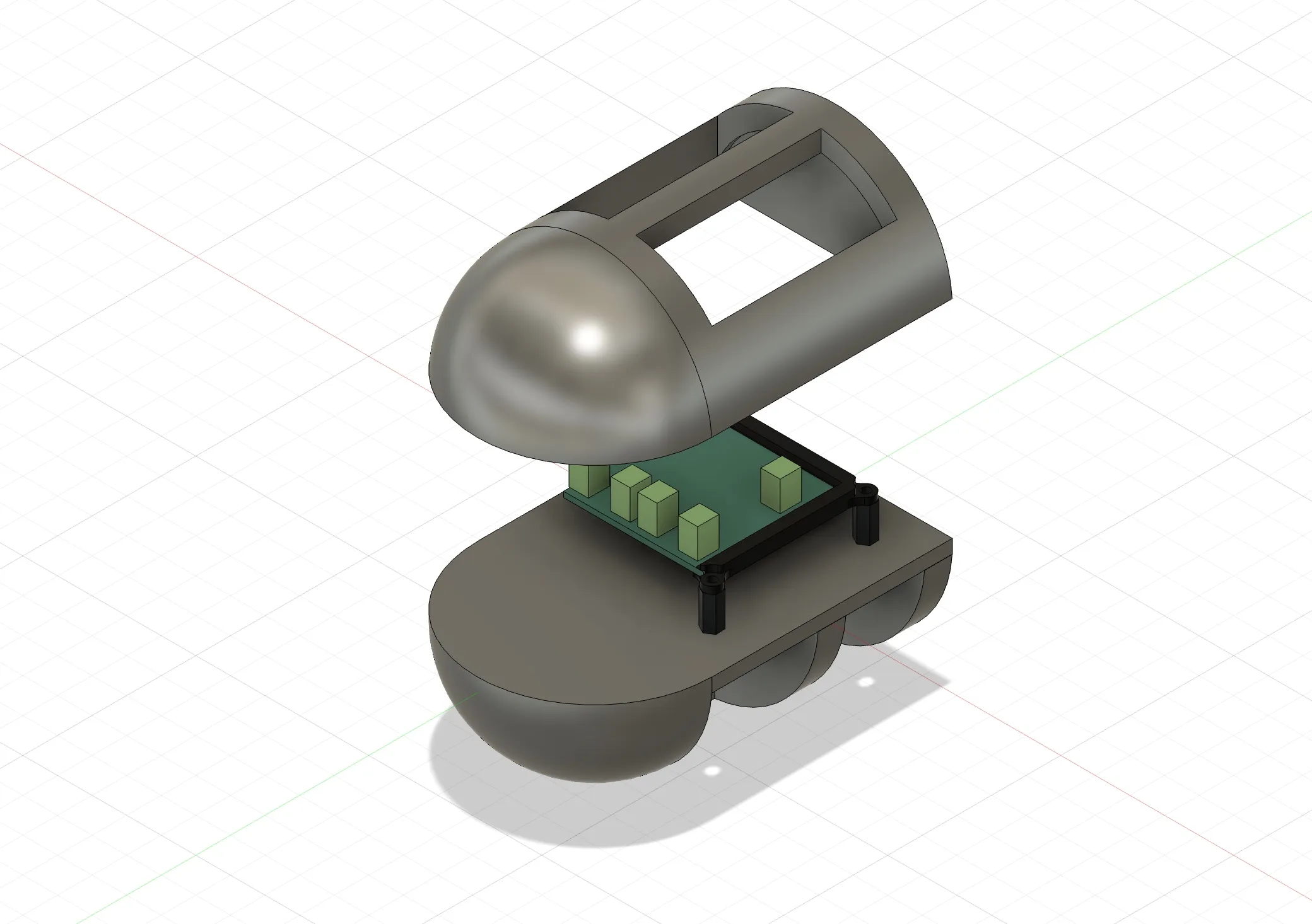
This design didn’t get far, as it didn’t use space efficiently and the exposed electronics wouldn’t have looked good. It was quickly replaced.
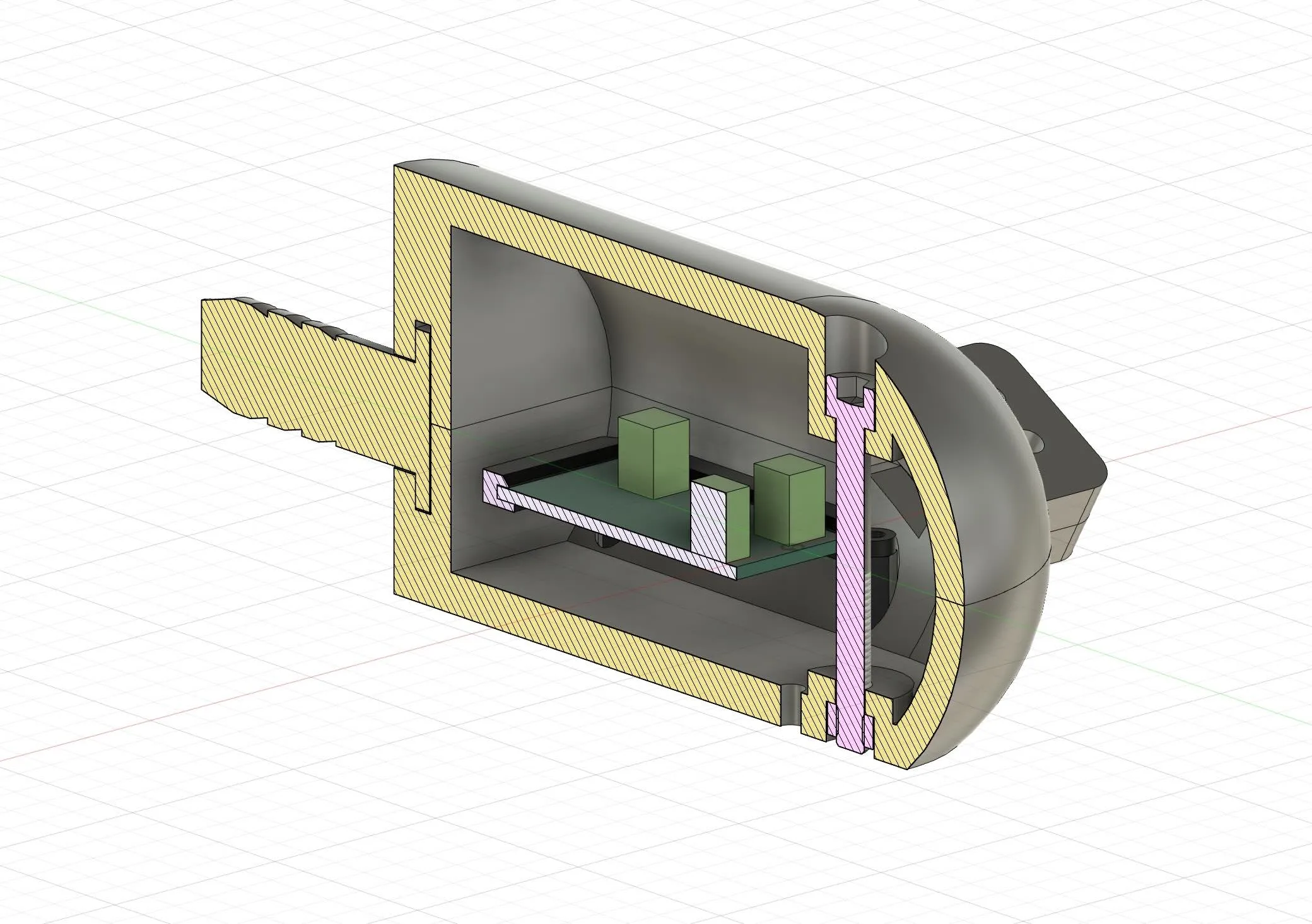
The next design is similar to the second, but the electronics were arranged in a way that kept the cylinder’s diameter to a minimum. It used no pegs; instead, most of the joints were handled with embedded nuts, for which I arrived at an optimal clearance of 0.2 mm.
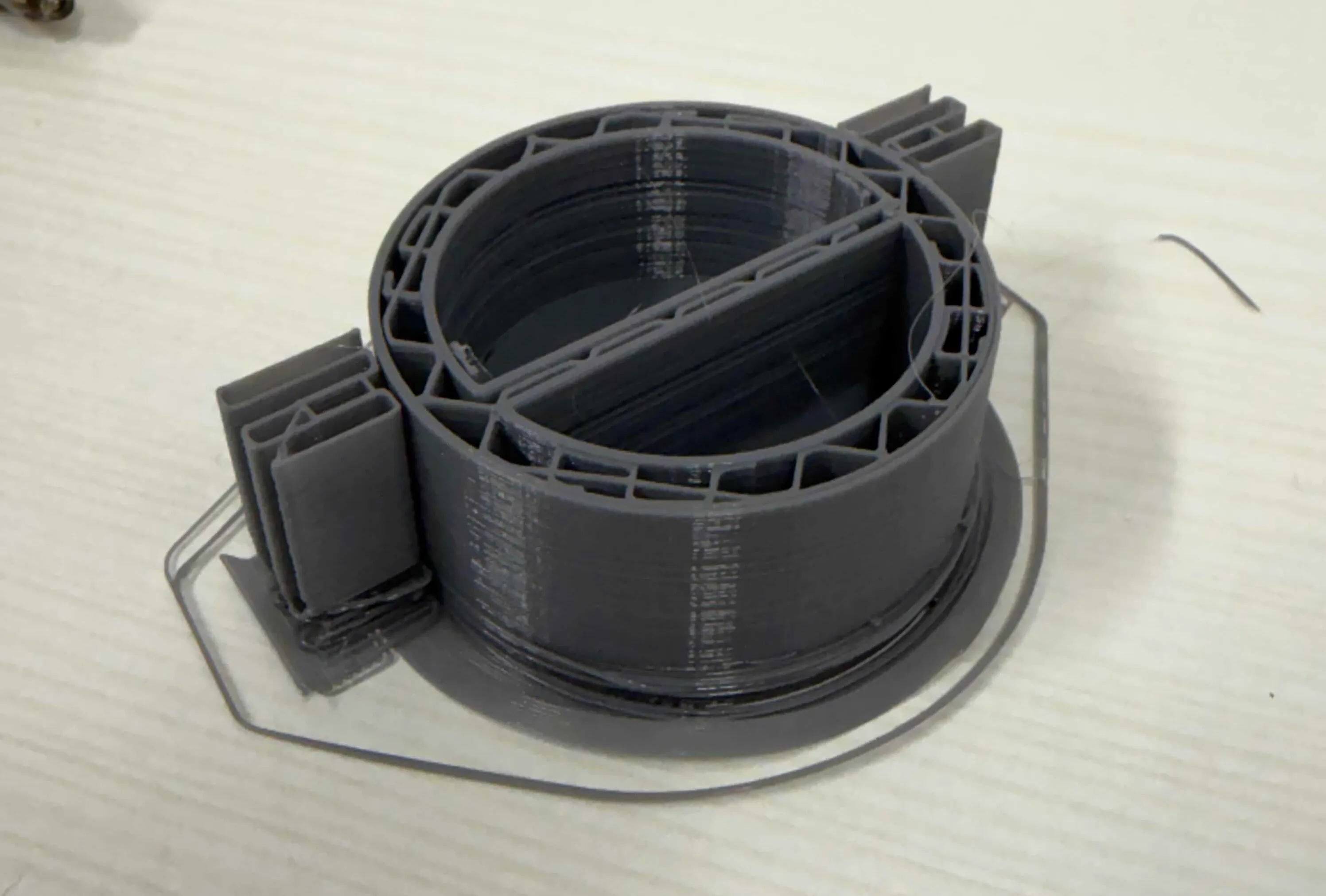
The first design also had trouble printing the protrusions for the IR sensors. Because they printed at an angle and on supports, they didn’t look good and the result was very imprecise. So for the third design I decided to print the protrusions separately and attach them to the main body with a dovetail joint. Since the dovetail had to print at an angle on the body, it wasn’t very precise, and in the end we used superglue to make everything hold better.
Most of the screws were chosen based on what I had on hand — mostly M2.5, plus a single M5×40 hex bolt I found in the scrap bin.
Overall, the final design solved the disassembly problem and held together reasonably well.